by Ben Berusch, Technical Supervisor, Hoffmann Innovations, Inc.
The purpose of this article is to demonstrate the AMP EFI MS3Pro Ultimate standalone engine control unit’s peak and hold injector control strategy to safely and properly control various types of automotive port injectors. I am specifically going to use the MS3Pro Ultimate in my demonstrations, but this same information is directly applicable to any automotive PCM/ECU/DME, standalone or factory OEM, that uses peak and hold style injector drivers. This article won’t directly apply to other technologies such as GDI (Gasoline Direct Injection) or any variant of diesel injection.
I’m going to try to keep the science talk to a minimum, but keep in mind, my goal here is to educate and inform. If we ignore the hard stuff, we won’t learn. I’ll try to balance out some of the more dry content with pictures, so please stay on board with me.
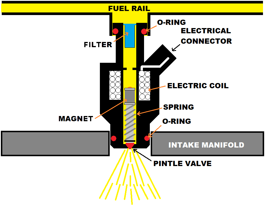
Before we move forward, we’re going to back up and talk about injectors. Your port fuel injector is essentially a solenoid with a magnetic valve. The injector has a 2-wire connector, one wire going to the vehicle’s battery positive post (via ignition switched relay), the other going to the ECU. The ECU’s internal processor will use its various sensors to determine fuel event scheduling. This calculation will determine when the fuel injection event should occur and for how long. When commanded to begin an injection event, the ECU uses an internal control circuit which grounds the the other wire, causing current to move through the injector’s electric coil. As current moves through the coil, a magnetic field develops inside the injector. This magnetic field draws the injector’s pintle valve up, allowing pressurized fuel to exit the injector and into the engine’s manifold, eventually working into the combustion chamber before it is ignited. When the ECU’s calculation determines that the injection event is over, the internal control circuit disconnects its ground to the injector. This causes the magnetic field inside the injector to collapse, and a spring returns the pintle to its closed position, ending the fuel delivery to the engine.
When working with gasoline port injection, it’s important to note that there are 2 types of injector control circuits, known as Saturated and Peak and Hold.
Saturated is probably the more common control method. It is simpler, requiring fewer components, and unsurprisingly has less cost associated with it. The MS3Pro Gen1 and MS3Pro Evo engine control units both use Saturated injector drive strategy. This relatively simple control scheme more or less just turns injectors “on” and “off” like a light switch. More “on” time means more fuel delivery. This works well with most injectors, particularly injectors known to have high impedance.
Peak and Hold is usually less commonly used because, as suggested above, the driver circuits become more complex. Directly related to complexity, the driver design will require more components, driving cost up. The higher parts count then takes up more space on the ECU’s printed circuit board (PCB). PCB space is usually limited and precious, so this tends to end up with larger ECU enclosure footprints. Depending on how the circuit is designed, it may also generate more heat, requiring additional heatsinking and/or creating other thermal challenges in the design. These things all add up in dollars and cents. However, some automotive fuel injectors require a Peak and Hold strategy, these are usually classified as low impedance injectors, and these days are pretty much used only in very high power applications – think alcohol fueled, multi-thousand horsepower engines.
If you are confused over if your injectors are high impedance or low impedance, this is easy to check with your multimeter. Disconnect your injector’s connector, and set your meter to resistance mode. Measure the resistance between the 2 pins on your injector’s connector. If it measures between 8 and 15 ohms, you have a high impedance injector. If it measures between 1 and 5 ohms, you have a low impedance injector. Impedance and resistance are similar concepts. Resistance describes a resistance to current flow. Impedance describes a resistance to the change of current flow. We can very easily measure the former and deduce the latter.

Why so complex? You can blame it on this guy named Georg Ohm, who stated that the current that goes through a conductor is directly proportional to the voltage.
I = V/R
Or Current (I) in Amperes = Voltage / Resistance
Current is defined as the flow of electric charge.
When it comes to your race car’s wiring, in many ways, current is your enemy. Higher current means larger gauge wiring in order to mitigate the heat created as current moves through the wire. Think about how the power feed to your fuel pump is 0 gauge or similar, but the wiring to your shift light is 20 gauge. The starter requires significantly higher current to operate.
Voltage is generally stable in a running automotive engine (before you call me out, let’s ignore brief transients from things like inrush when a cooling fan activates). Most applications run around 14 volts. Did you test the resistance of your injector earlier? Let’s say you did, and you measured 12 ohms. Using Ohm’s Law, we can calculate
I = 14 volts / 12 ohms
I = 1.2 amps
A typical high impedance injector will sink between 1 and 1.5 amps of current. This is a relatively low amount of current, think shift light. It doesn’t build up much heat.
Let’s say you measure a low impedance injector and find it has 2 ohms or resistance. In this case,
I = 14 volts / 2 ohms
I = 7 amps
7 amps is a lot of current compared to our high impedance injector example, roughly 6x as much. Think starter motor in this regard. If controlled in an on/off fashion, our injector would sink a lot of current throughout the commanded injection event. The wiring to the injector would need to be very beefy, adding weight to the car, and the electrical demand would be tough on the vehicle’s charging system The high level of current moving through the ECU itself may causing a lot of internal heat build up. It would also cause a lot of heat to build up inside the injector, potentially heating the fuel, and over time the heat may damage the injector itself. Weight is our enemy and heat is our enemy. What can we do to fix this?
Introducing Peak and Hold. A Peak and Hold injector driver is far more complex than simply turning the injector on and off. The Peak and Hold strategy has 2 main phases of activity.
1: The Peak.
The peak phase is a quick burst of high current. This burst of current causes the magnetic field inside the injector to develop rapidly, which shortens the time required for the field to pull the pintle valve open. This reduction of injector dead time allows for more precise injector control via quicker injector opening action. The peak current is generally 4 or 8 amps and is very short duration, typically lasting only 1 or 2 milliseconds.
2: The Hold.
Once the pintle valve is open, substantially less magnetic field is required to keep the valve open. In this phase, the ECU will ramp down the current being delivered to the injector. This lowers the average current sinked by the injector, allowing the wiring harness to be constructed with smaller gauge wiring, and reducing the amount of heat produced by the injector and potentially convected into the fuel. During the hold period, the ECU may actively measure the current delivered to the injector, rapidly switching its driver circuit on and off, in order to maintain the desired level of hold current. Hold current is generally 1 or 2 amps, and the duration of the hold phase is dependent on the pulsewidth commanded by the ECU and can be substantially longer than the peak phase.
Here is an example of the Peak and Hold driver circuit as used in the MS3Pro Ultimate in action. I am commanding a 5 millisecond duration fuel injection event while measuring the result with an oscilloscope. My injector is a common automotive 120 lb/hr low impedance injector, which measures 2.4 ohms resistance. The pink trace represents voltage at the injector, measured in Volts. The blue trace represents current sinked by the injector, measured in Amps. The scope capture shows how both voltage and current change over time during the injection event. Note that the Y-axis scale is in Volts. You can see before the injection event begins, we are measuring our battery voltage of 14V. When the ECU begins the injection event, our scope will show 0V, as the circuit has been completed. As we transition into our Hold phase of the event, you will see the ECU begins to actively control current. It does this by rapidly switching the injector circuit on and off at a very high speed. The rapid switching speed is so quick, and the built in delay of the injector is so slow, the injector is unable to close and re-open during the events.
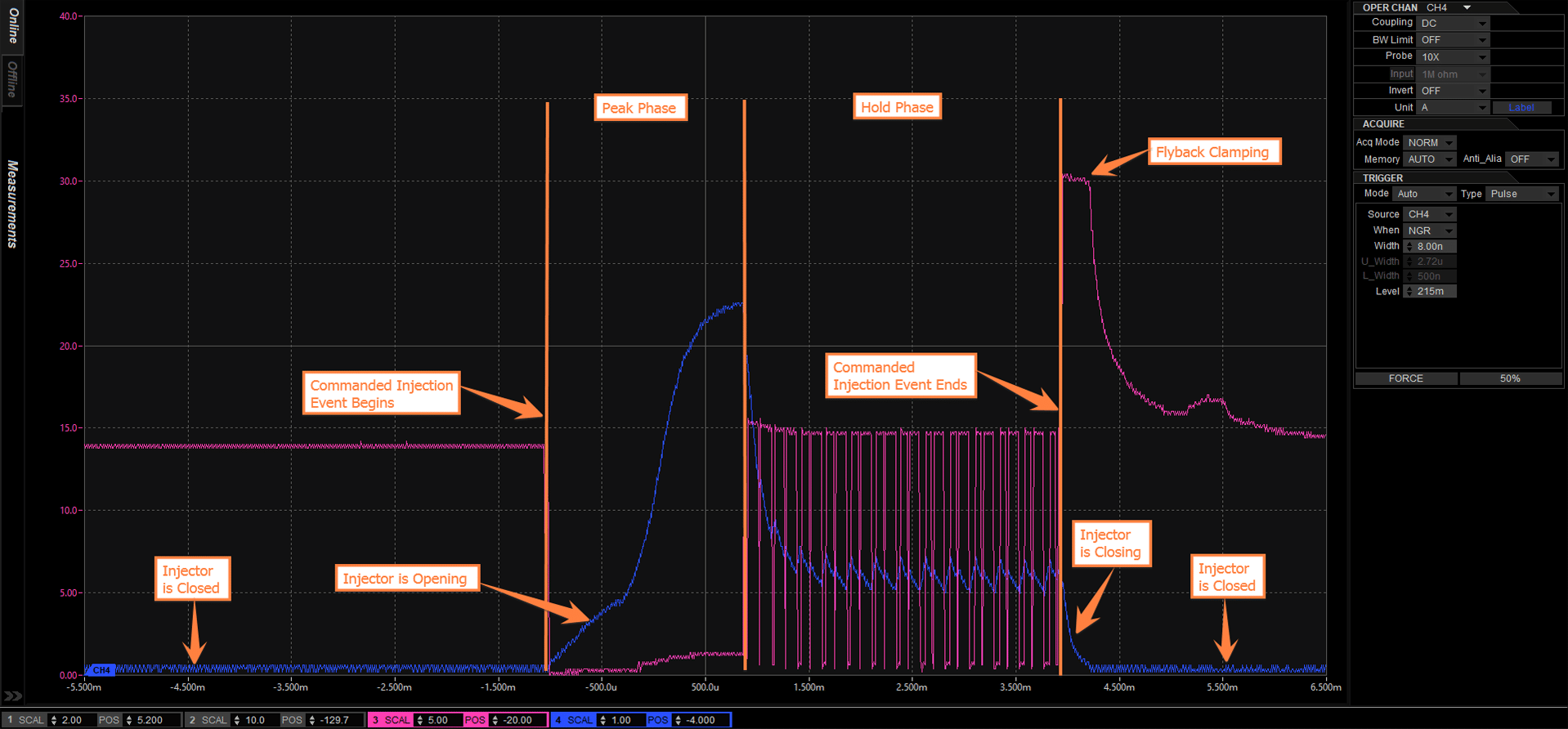
Note the pink trace, which is voltage measured at the injector. When the ECU’s injector driver is providing ground to the injector, our oscilloscope will measure 0V at the injector. When the ECU is not providing ground, we will measure our power supply voltage, 14V in this case. So you will see before our scheduled fueling event occurs, we measure 14V. When the event begins and we enter the Peak phase, we measure 0V. As we enter the Hold phase, we see the ECU rapidly switching this ground. Note the pink square waves, showing the voltage measurement rapidly switching between 14V and 0V.
Next, note the blue trace, our current measured at the injector. When the voltage is measured at 0V (injector circuit is grounded), current increases. When the voltage is measured at 14V (injector circuit is not grounded), current decreases. The MS3Pro Ultimate’s injector driver is actively monitoring and controlling the current at the injector by switching the injector’s ground on and off to maintain the desired level of current. With this ECU, we target 4.5 Amps during the Peak phase and 1.1 Amps during the Hold phase when the ECU is in “4:1” mode.
Here is a different view. I have changed the Y-axis scale to match the blue trace, which is our current sinked at the injector, measured in Amps.
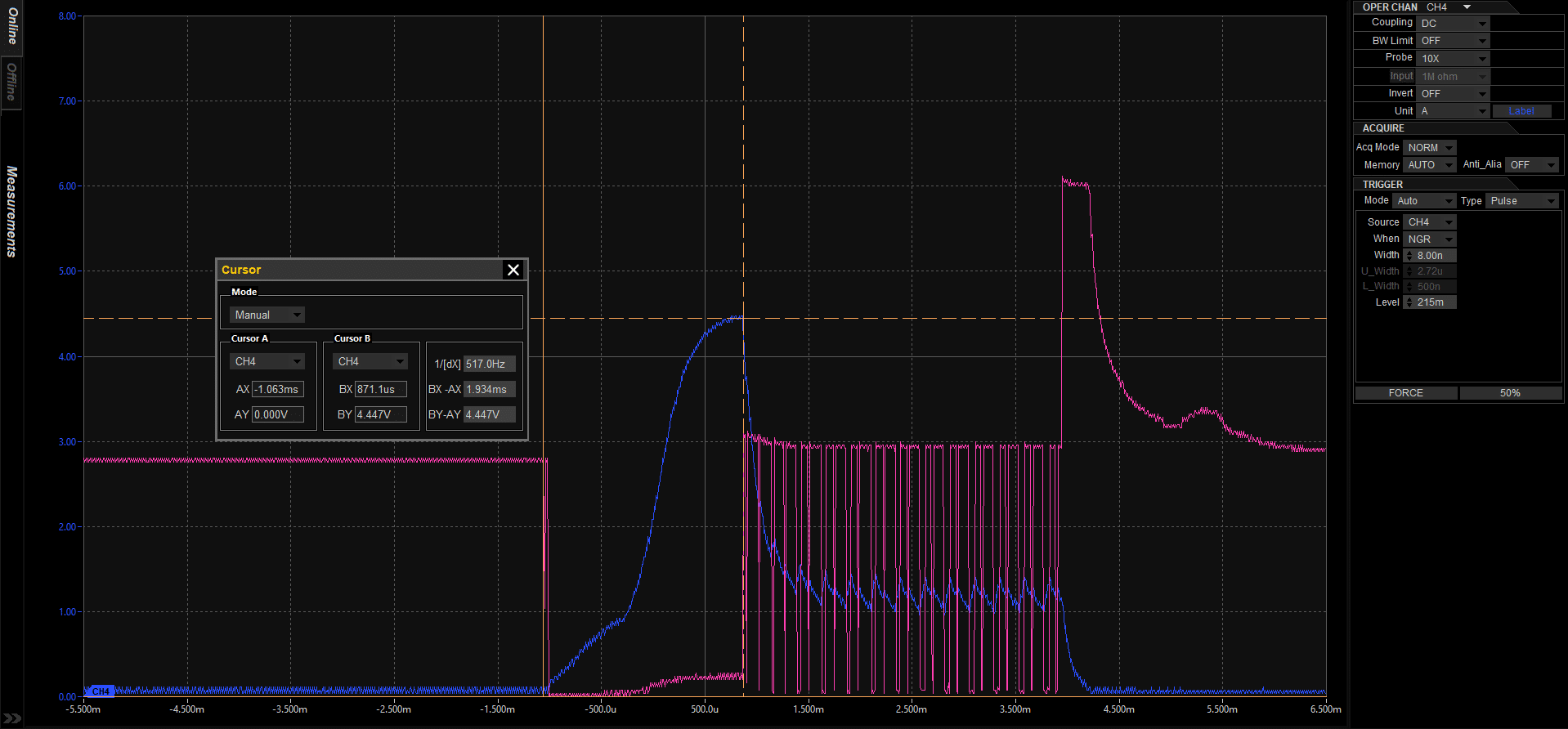
You can see that our Peak phase is 1.9 milliseconds in duration, and the injector sinked a maximum of about 4.5 amps during the Peak. The Hold phase begins after 1.9 milliseconds and has a duration of approximately 3.1 milliseconds, to round out our 5 millisecond duration commanded event. During the Hold phase, the ECU is actively monitoring current, and is maintaining an average of 1.1 amps.
I hope that you found the information in this article helpful. If you have questions, comments, or feedback (good and bad!), please send me an email: [email protected]
Regards,
Ben Berusch
AMP EFI
Technical Support